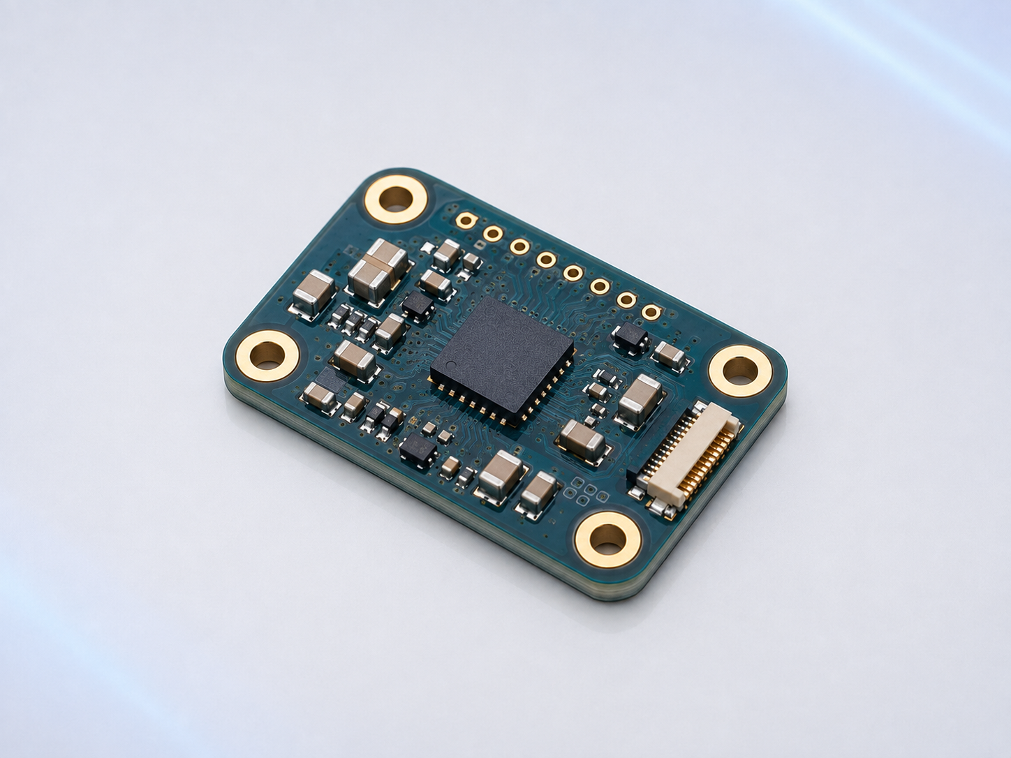
The accelerometer sensor module is designed to measurelinear acceleration, tilt, vibration and mechanical shock in robotic systems.It detects movement along the X, Y and Z axes and provides real-time motiondata to the robot’s control system.
Based on compact MEMS technology, the module offers fastresponse, stable sensing performance and easy integration intospace-constrained robotic platforms. The collected acceleration data cansupport motion control, condition monitoring, collision detection and attitudeestimation. It can also be combined with gyroscopes, encoders and other sensorsfor more accurate sensor-fusion solutions.
The module is suitable for industrial robots, humanoidrobots, robotic arms, AGVs, AMRs, robot dogs, drones and autonomous inspectionequipment. Measurement range, sensitivity, communication interface and PCBconfiguration can be customized according to project requirements.
Key Applications
Three-axis linear acceleration measurement
Robot tilt and inclination detection
Vibration and condition monitoring
Shock and collision detection
Motion and activity tracking
Robotic arm movement monitoring
Navigation and attitude estimation
Predictive maintenance
Multi-sensor data fusion
Main Advantages
Compact MEMS sensor design
Three-axis motion detection
Fast response to movement and impact
Stable measurement performance
Suitable for dynamic robotic environments
Easy integration with robot control systems
Customizable PCB and interface options
Main Components of the Accelerometer Module
Component | Function |
Three-Axis MEMS Accelerometer | Measures linear acceleration along the X, Y and Z axes. It can also detect gravity, tilt, vibration, impact and changes in motion. |
MEMS Sensing Structure | Contains a microscopic movable proof mass. Acceleration causes the proof mass to move, producing a measurable electrical change. |
Sensor ASIC | Drives the MEMS sensing structure, amplifies the original signal and performs internal signal processing. It is normally integrated with the MEMS sensor. |
Analog-to-Digital Converter | Converts the analog sensing signal into digital acceleration data. It is usually integrated into the accelerometer IC. |
Temperature Sensor | Measures internal temperature and supports compensation for temperature-related offset and sensitivity changes. |
Digital Filter | Reduces noise and unwanted vibration frequencies. It may be integrated into the sensor IC or implemented by an external processor. |
MCU or Processing IC—Optional | Performs calibration, data filtering, event detection, diagnostics and communication management. |
Voltage Regulator | Provides stable operating voltage for the sensing and processing circuits. |
Crystal or Oscillator—Optional | Provides an accurate timing reference for sampling and data processing. Many accelerometers contain an internal oscillator. |
Flash Memory or EEPROM—Optional | Stores calibration coefficients, threshold settings and configuration parameters. |
Interface and Level-Shifting Circuit | Connects the module to the robot controller and matches different communication-voltage levels. |
ESD and Input-Protection Components | Protect the module against electrostatic discharge, reverse polarity and voltage transients. |
Precision Resistors and Capacitors | Provide power filtering, signal filtering, pull-up resistance and stable operation. |
Board-to-Board Connector | Carries power, ground, data, interrupt and diagnostic signals. |
PCB and Mounting Holes | Provide electrical connections and secure mechanical installation inside the robot. |
How the Accelerometer Works
A MEMS accelerometer contains a microscopic movable proofmass suspended by very small structures. When the robot accelerates,decelerates, tilts or experiences vibration, the proof mass moves relative tothe sensor frame.
This movement changes the internal capacitance. The sensorelectronics measure the change and convert it into acceleration data for the X,Y and Z axes.
The output is normally expressed in:
g, where 1 g represents standard gravitational acceleration
m/s², metres per second squared
Because an accelerometer also detects gravity, it canestimate tilt when the robot is stationary or moving slowly.
Main Functions
Three-axis linear-acceleration measurement
Tilt and inclination detection
Gravity-vector detection
Motion and activity detection
Vibration monitoring
Shock and collision detection
Fall and abnormal-motion detection
Motor and gearbox condition monitoring
Navigation assistance
Multi-sensor data fusion
Axis Configurations
Configuration | Typical Use |
Single-Axis Accelerometer | Measures acceleration along one defined direction, such as machine vibration or linear movement. |
Dual-Axis Accelerometer | Measures acceleration in two directions for specialized motion-control applications. |
Three-Axis Accelerometer | Measures acceleration along the X, Y and Z axes and is commonly used in robotic systems. |
Integrated Detection Features
Depending on the selected accelerometer, the module maysupport:
Motion and inactivity detection
Free-fall detection
Tap or impact detection
Orientation-change detection
Programmable acceleration thresholds
Vibration alarms
Data-ready interrupt
FIFO data storage
Low-power wake-up function
Self-test and diagnostic functions
Communication Interfaces
The accelerometer module can be configured with:
I²C and SPI are commonly used for board-level integration.CAN and RS-485 are more suitable for longer cables and electrically noisyrobotic environments.
Recommended Specifications for the Product Page
Specification | Description |
Number of Axes | Single-axis, dual-axis or three-axis |
Measurement Range | Maximum positive and negative acceleration that can be measured |
Sensitivity | Change in sensor output corresponding to a specific acceleration |
Resolution | Smallest detectable change in acceleration |
Offset or Zero-g Bias | Sensor output when no external acceleration is applied apart from gravity |
Noise Density | Noise level contained in the acceleration output |
Bandwidth | Range of vibration or motion frequencies the sensor can measure |
Output Data Rate | Number of acceleration updates per second |
Nonlinearity | Deviation from an ideal linear response |
Cross-Axis Sensitivity | Response on one axis caused by acceleration along another axis |
Temperature Drift | Change in offset or sensitivity over temperature |
Shock Survivability | Maximum mechanical shock the sensor can withstand without damage |
Interface | I²C, SPI, UART, CAN, RS-485 or analog output |
Supply Voltage | Required input voltage |
Power Consumption | Typical and maximum current consumption |
Operating Temperature | Supported environmental temperature range |
Dimensions | PCB length, width and height |
Calibration | Factory calibration or user-calibration options |
Installation Considerations
Mount the module firmly on a rigid part of the robot.
Align the X, Y and Z axes with the robot coordinate system.
Record the mounting orientation in the control software.
Avoid flexible mounting surfaces that can introduce unwanted movement.
Keep the module away from excessive motor and gearbox vibration when measuring body motion.
Place it close to the vibration source when performing condition monitoring.
Use mechanical isolation only when it does not remove the frequencies that must be measured.
Keep sufficient distance from high-current motor cables and switching circuits.
Use stable power, grounding and appropriate filtering.
Perform offset and axis calibration after installation.
Consider gravity compensation when calculating the robot’s actual linear acceleration.
Important Technical Note
An accelerometer directly measures specific force,including the effect of gravity. It does not directly measure velocity,distance or absolute position.
Velocity and displacement can be estimated by integratingacceleration data, but even small offset and noise errors accumulate over time.For accurate navigation, accelerometer data should normally be combined withgyroscope, encoder, vision or positioning data through sensor fusion.


