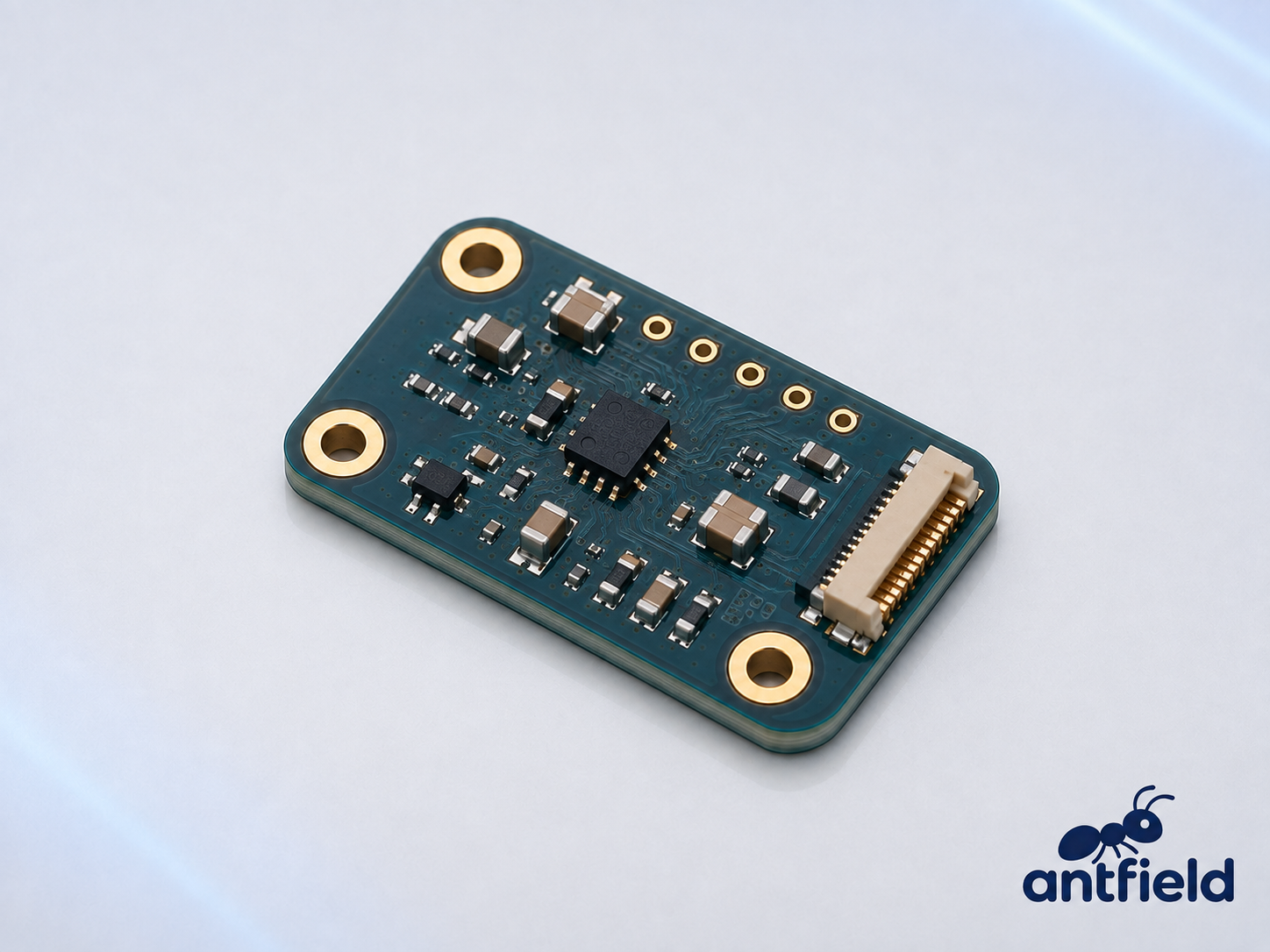
The Hall-effect sensor module is designed to detectmagnetic fields and provide reliable, non-contact position and motion feedbackfor robotic systems. It can be used to measure the position, speed androtational direction of magnetic targets without physical contact or mechanicalwear.
In robot joint motors, Hall sensors detect changes in themagnetic field generated by the rotor or magnetic encoder ring. The resultingfeedback helps the motor controller perform accurate commutation, speedregulation and position control.
Its compact PCB design allows easy integration into roboticjoints, brushless motors, actuators and other space-constrained assemblies.Sensing range, output type, interface and PCB configuration can be customizedaccording to specific application requirements.
Key Applications
Robot joint position detection
Brushless motor commutation
Rotor speed and direction sensing
Magnetic encoder feedback
Non-contact proximity detection
End-position and limit detection
Linear actuator position monitoring
Wheel and motor speed measurement
Magnetic current sensing, depending on configuration
Main Advantages
Non-contact magnetic sensing
No mechanical wear
Fast and stable response
Suitable for dusty or enclosed environments
Compact and easy to integrate
Reliable operation over repeated motion cycles
Customizable sensing and interface options
Main Components of the Hall Sensor Module
Component | Function |
Hall-Effect Sensor IC | Detects the presence, strength or direction of a magnetic field and converts it into an electrical signal. |
Hall Sensing Element | A semiconductor structure inside the sensor IC that generates a small voltage when exposed to a magnetic field. |
Permanent Magnet or Magnetic Target | Generates the magnetic field detected by the sensor. It is normally installed on the motor shaft, rotor, actuator or moving mechanism rather than on the stationary PCB. |
Signal Amplifier | Amplifies the small Hall voltage produced by the sensing element. It is often integrated into the Hall sensor IC. |
Comparator—Optional | Compares the magnetic-field signal with a defined threshold and produces a digital ON/OFF output. |
Analog-to-Digital Converter—Optional | Converts the analog magnetic-field signal into digital measurement data. |
Temperature-Compensation Circuit | Reduces changes in sensitivity and switching points caused by temperature variation. It is often integrated into the sensor IC. |
MCU or Processing IC—Optional | Performs filtering, calibration, position calculation, speed calculation and communication management. |
Voltage Regulator | Provides a stable operating voltage for the sensor and processing circuits. |
Output Driver | Generates analog, open-drain, push-pull, PWM or communication output signals. |
Oscillator—Optional | Provides a timing reference for digital processing and communication. |
Flash Memory or EEPROM—Optional | Stores calibration coefficients, switching thresholds, zero-position settings and configuration parameters. |
ESD and Input-Protection Components | Protect the module against electrostatic discharge, reverse polarity, overvoltage and electrical transients. |
Precision Resistors and Capacitors | Provide power filtering, signal filtering, pull-up resistance and stable circuit operation. |
Board-to-Board Connector | Carries power, output, communication and diagnostic signals to the robot controller. |
PCB and Mounting Holes | Provide electrical connections and secure mechanical positioning relative to the magnet. |
How the Hall Sensor Works
When electrical current flows through a Hall sensingelement and a magnetic field is applied perpendicular to it, a small voltage isgenerated across the element. This is known as the Hall effect.
The sensor IC amplifies and processes this voltage todetect:
Magnetic-field presence
Magnetic-field strength
North or south magnetic polarity
Position of a magnetic target
Rotor or shaft movement
Rotation speed and direction
Because the sensor and magnetic target do not need physicalcontact, Hall sensors can operate without mechanical sensing wear.
Hall Sensor Types
Sensor Type | Output and Function | Typical Robotic Use |
Hall Switch | Changes between ON and OFF when the magnetic field crosses a threshold | Limit detection, proximity sensing and homing |
Hall Latch | Changes state with one magnetic pole and resets with the opposite pole | BLDC motor commutation and rotation detection |
Linear Hall Sensor | Produces an analog output proportional to magnetic-field strength | Position, displacement and current sensing |
Digital Hall Sensor | Converts magnetic measurements into digital data | Precise position and diagnostic monitoring |
Hall Angle Sensor | Measures the direction of a rotating magnetic field | Shaft angle and robot joint-position detection |
Multi-Axis Hall Sensor | Measures magnetic fields along two or three axes | Joysticks, complex position sensing and robotic joints |
Main Functions
Non-contact position detection
Proximity and presence detection
Motor-rotor position sensing
Rotational-speed measurement
Rotation-direction detection
BLDC motor commutation
Joint-limit and end-position detection
Homing and reference-position detection
Magnetic-angle measurement
Linear displacement detection
Contactless switching
Applications
Humanoid robot joints
Industrial robotic arms
BLDC motors
Servo motors and actuators
Robot grippers
AGV and AMR wheel drives
Robot steering systems
Linear actuators
Robot doors and covers
Limit and safety switches
Robot charging systems
Magnetic encoder assemblies
Output and Interface Options
Depending on the selected sensor and module design, theHall sensor can support:
For simple proximity detection, digital switch outputs areusually sufficient. Angle, position and diagnostic applications may requireanalog or digital communication interfaces.
Recommended Specifications for the Product Page
Specification | Description |
Sensor Type | Switch, latch, linear, angle or multi-axis Hall sensor |
Magnetic Range | Minimum and maximum measurable magnetic-field strength |
Operate Point | Magnetic-field level that activates the sensor output |
Release Point | Magnetic-field level that returns the output to its original state |
Hysteresis | Difference between the operate and release thresholds |
Sensitivity | Output change corresponding to a change in magnetic field |
Resolution | Smallest detectable magnetic-field or position change |
Accuracy | Difference between the measured and actual value |
Bandwidth | Maximum magnetic-field or motion frequency that can be measured |
Response Time | Time required for the output to react to a magnetic-field change |
Temperature Drift | Change in sensitivity or switching point over temperature |
Air Gap | Recommended distance between the sensor and magnetic target |
Output Type | Analog, digital, PWM or communication output |
Supply Voltage | Required operating voltage |
Power Consumption | Typical and maximum current consumption |
Operating Temperature | Supported environmental temperature range |
Protection Features | ESD, reverse-polarity and transient protection |
Dimensions | PCB length, width and height |
Installation Considerations
Maintain the specified distance between the sensor and magnet.
Confirm the required magnetic polarity and orientation.
Align the sensor’s sensitive axis with the magnetic-field direction.
Secure the PCB to prevent movement or vibration.
Keep the sensing area away from unintended permanent magnets.
Consider magnetic interference from motors, speakers and high-current cables.
Avoid large ferromagnetic parts near the sensing path where possible.
Verify the magnetic-field strength across the complete operating distance.
Consider shaft runout and mechanical tolerances in rotary applications.
Perform calibration after final mechanical assembly.
Use stable power, grounding and appropriate filtering.
Select a magnet material suitable for the operating-temperature range.
Important Technical Note
The Hall sensor PCB is normally the stationarysensing component, while the permanent magnet is installed on themoving mechanical part.
A Hall sensor detects magnetic fields directly. Position,speed and direction are calculated from changes in the magnetic signal. Thefinal accuracy therefore depends on the sensor IC, magnet strength, air gap,mechanical alignment, temperature and surrounding magnetic materials.


