
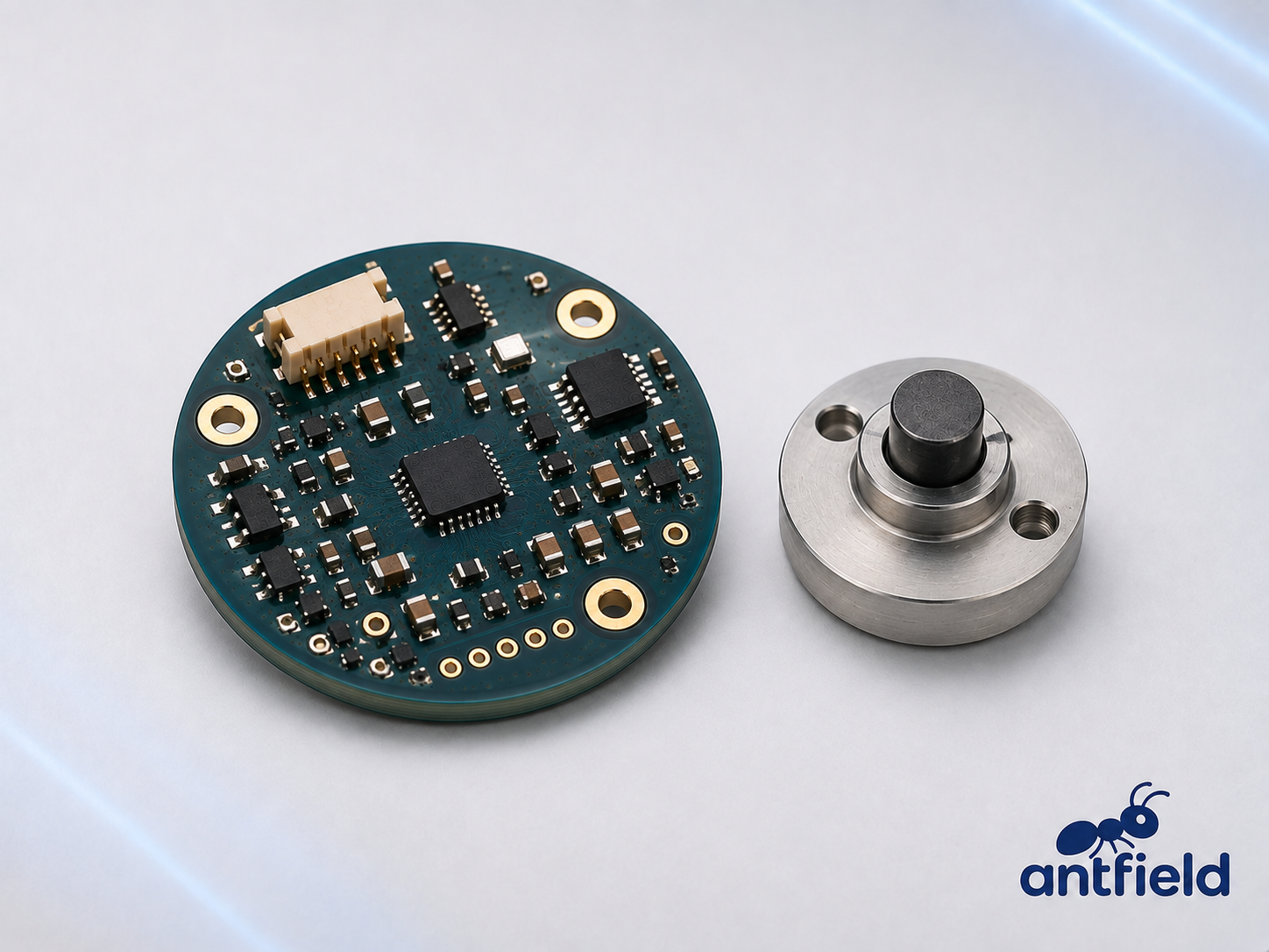
The Antfield Magnetic Absolute Rotary Encoder Module isdesigned to provide accurate position, speed and direction feedback for roboticjoints, servo motors and rotary actuators.
A magnetic rotor hub is installed on the rotating shaft,while the encoder PCB remains fixed to the motor or robot housing. As the shaftrotates, the magnetic angle sensor detects changes in the magnetic-fielddirection and converts them into digital angular-position data.
Unlike an incremental encoder, an absolute encoder canprovide the shaft’s angular position immediately after power-up withoutrequiring a homing movement. This makes it suitable for humanoid robots,robotic arms and other systems that require reliable joint-positioninformation.
Resolution, accuracy, communication interface, rotationspeed, supply voltage, mechanical dimensions and PCB configuration can becustomized according to project requirements.
Main Functions
Absolute angular-position measurement
Rotational-speed measurement
Rotation-direction detection
Robot joint-position feedback
Servo closed-loop control
Motor commutation support
Zero-position and reference detection
Joint-limit monitoring
Motion synchronization
Position-error detection
Predictive-maintenance support
Applications
Humanoid robot joints
Industrial robotic arms
Servo motors
Joint actuators
Robot grippers
AGV and AMR drive wheels
Robot steering systems
Collaborative robots
Robot dogs and legged robots
Gimbal and camera-positioning systems
Medical and rehabilitation robots
Automated rotary platforms
Main Components
Component | Function |
Magnetic Rotor Hub | Attaches to the rotating motor or joint shaft and carries the permanent magnet. |
Diametrically Magnetized Magnet | Generates a rotating magnetic field corresponding to the shaft angle. |
Magnetic Angle-Sensor IC | Detects the direction of the rotating magnetic field and calculates the shaft position. |
Signal-Processing ASIC or MCU | Processes sensor data, performs filtering and generates position, speed and direction information. |
ADC—Usually Integrated | Converts the magnetic sensor’s analog signal into digital position data. |
Crystal or Oscillator | Provides an accurate timing reference for position sampling and communication. |
Flash Memory or EEPROM | Stores calibration coefficients, zero-position settings and configuration parameters. |
Voltage Regulator | Provides stable operating voltage to the sensor and processing circuits. |
Communication Transceiver | Supports communication between the encoder and robot controller. |
ESD and Input-Protection Components | Protect against electrostatic discharge, reverse polarity and voltage transients. |
Precision Resistors and Capacitors | Provide power filtering, signal conditioning and stable circuit operation. |
Board-to-Board Connector | Carries power, position data, communication and diagnostic signals. |
Circular PCB | Provides the mechanical and electrical platform for the encoder electronics. |
Mounting Bracket and Fasteners | Hold the stationary PCB in precise alignment with the rotating magnet. |
Encoder Types
Encoder Type | Characteristics |
Incremental Encoder | Produces pulses as the shaft rotates. Position is calculated by counting pulses and normally requires a reference or homing procedure after power-up. |
Absolute Encoder | Provides a unique position value for each shaft angle and retains position information after power interruption. |
Magnetic Encoder | Uses a permanent magnet and magnetic-field sensor. It is compact and resistant to dust, oil and vibration. |
Optical Encoder | Uses an optical disk, LED and photodetector. It can provide high resolution but is more sensitive to contamination and alignment. |
Communication Interfaces
Depending on the selected configuration, the encoder cansupport:
SPI
I²C
PWM
Analog output
Quadrature A/B/Z output
SSI
BiSS-C
UART
CAN or CAN FD
RS-485
SPI, SSI and BiSS-C are commonly used for fast positionfeedback. CAN and RS-485 are suitable for distributed robotic systems andlonger communication distances.
Main Advantages
Absolute position available immediately after power-up
Non-contact magnetic measurement
No mechanical sensing wear
Compact design for robotic joints
Supports position, speed and direction feedback
Resistant to dust, oil and vibration
Suitable for high-cycle robotic movement
Flexible output and communication options
Customizable PCB and mechanical dimensions
Installation Considerations
Keep the magnet and sensor concentrically aligned with the shaft.
Maintain the specified axial air gap between the magnet and sensor.
Prevent the stationary PCB from rotating with the shaft.
Avoid ferromagnetic parts close to the sensing area where possible.
Keep the encoder away from strong external magnetic fields.
Confirm magnet polarity and orientation before assembly.
Calibrate the zero position after mechanical installation.
Control shaft runout, tilt and mounting tolerances.
Use stable power, grounding and signal filtering.
Select an interface suitable for the cable length and electrical-noise environment.

