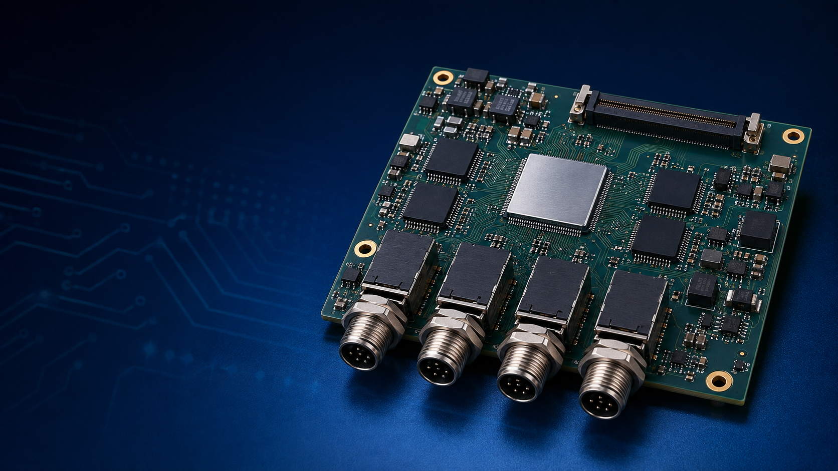
Key Features
Differential noise-resistant communication
Galvanic isolation option
Bus protection and termination
Compact node or gateway implementation
Typical Electronic Components
CAN controller; CAN/CAN FD transceiver; digital isolator; isolated DC-DC; common-mode choke; TVS; termination network.
Reference PCB and PCBA Parameters
Reference item | Typical guidance |
Typical layers | 2-6 layers |
Differential impedance | Commonly 120 ohm nominal at cable system level |
Data rate | Protocol-, topology- and cable-dependent |
Isolation | Optional, selected by grounding architecture |
Protection | ESD, EFT and surge based on environment |
Testing | Communication, error-frame, termination and EMC pre-check |
Manufacturing and Engineering Priorities
Route CAN_H and CAN_L together with a continuous return reference.
Place transceiver, protection and connector in a controlled sequence.
Terminate only according to the actual bus topology.
Evaluate stub length, node count, cable and data rate together.
Design and Commercial Cautions
Do not imply that every PCB trace alone is a 120-ohm cable termination system. Ground isolation strategy must match the complete robot harness. Use automotive-grade components only when required and properly qualified.
|
Applications
Distributed joints, mobile bases, BMS, servo axes and sensor networks.

