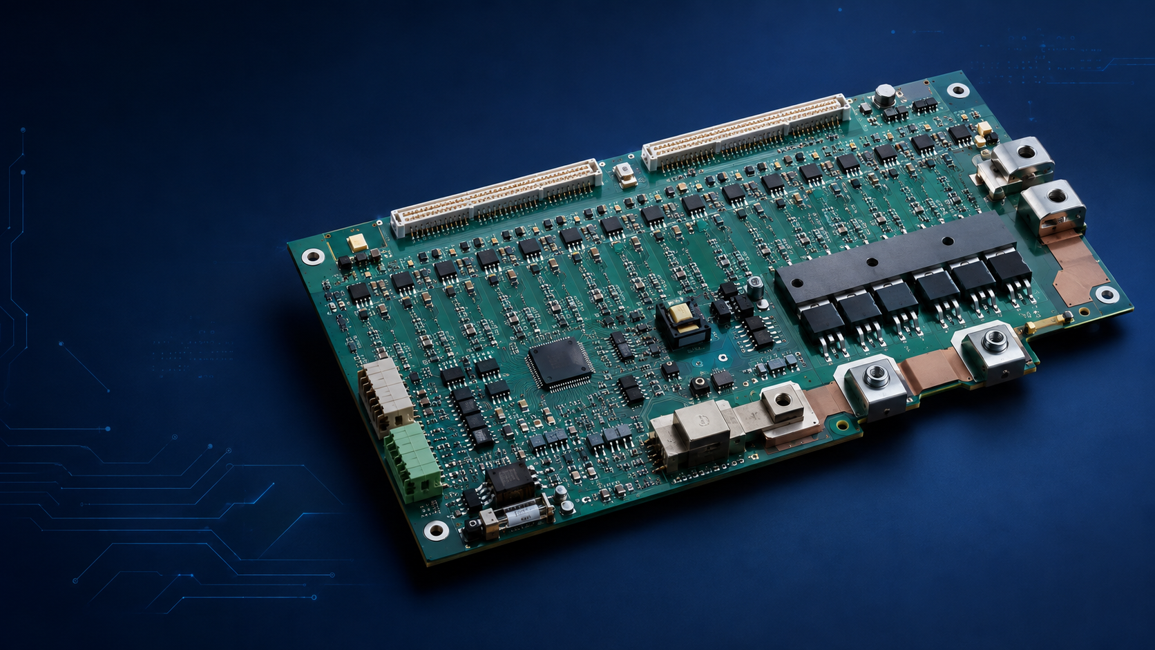
Key Features
Cell voltage and temperature monitoring
Charge/discharge and short-circuit protection
Passive or active balancing
State-of-charge and health estimation
Typical Electronic Components
Battery-monitor IC; safety protector; MCU; shunt/Hall sensor; balancing resistors/MOSFETs; contactor drivers; isolation; CAN/UART.
Reference PCB and PCBA Parameters
Reference item | Typical guidance |
Cell count | Project-specific; selected by battery architecture |
Typical layers | 4-8 layers |
Copper | 2-6 oz for current paths as needed |
Isolation | Defined by pack voltage and safety concept |
Key processes | Heavy copper, creepage control, conformal coating |
Testing | Cell simulation, balancing, protection and charge/discharge test |
Manufacturing and Engineering Priorities
Route cell measurements as a quiet, ordered sensing network.
Use Kelvin connections for pack current measurement.
Define safe-state behavior for contactors, MOSFETs and communication loss.
Coordinate thresholds with cell chemistry, pack design and charger.
Design and Commercial Cautions
BMS performance and safety depend on cells, pack mechanics, wiring, software and charger - not the PCB alone. Battery transport and product certification are separate from PCBA manufacturing. Require written approval for protection-threshold or component changes.
|
Applications
AGV/AMR, delivery, cleaning, service, robot dog and humanoid platforms.

