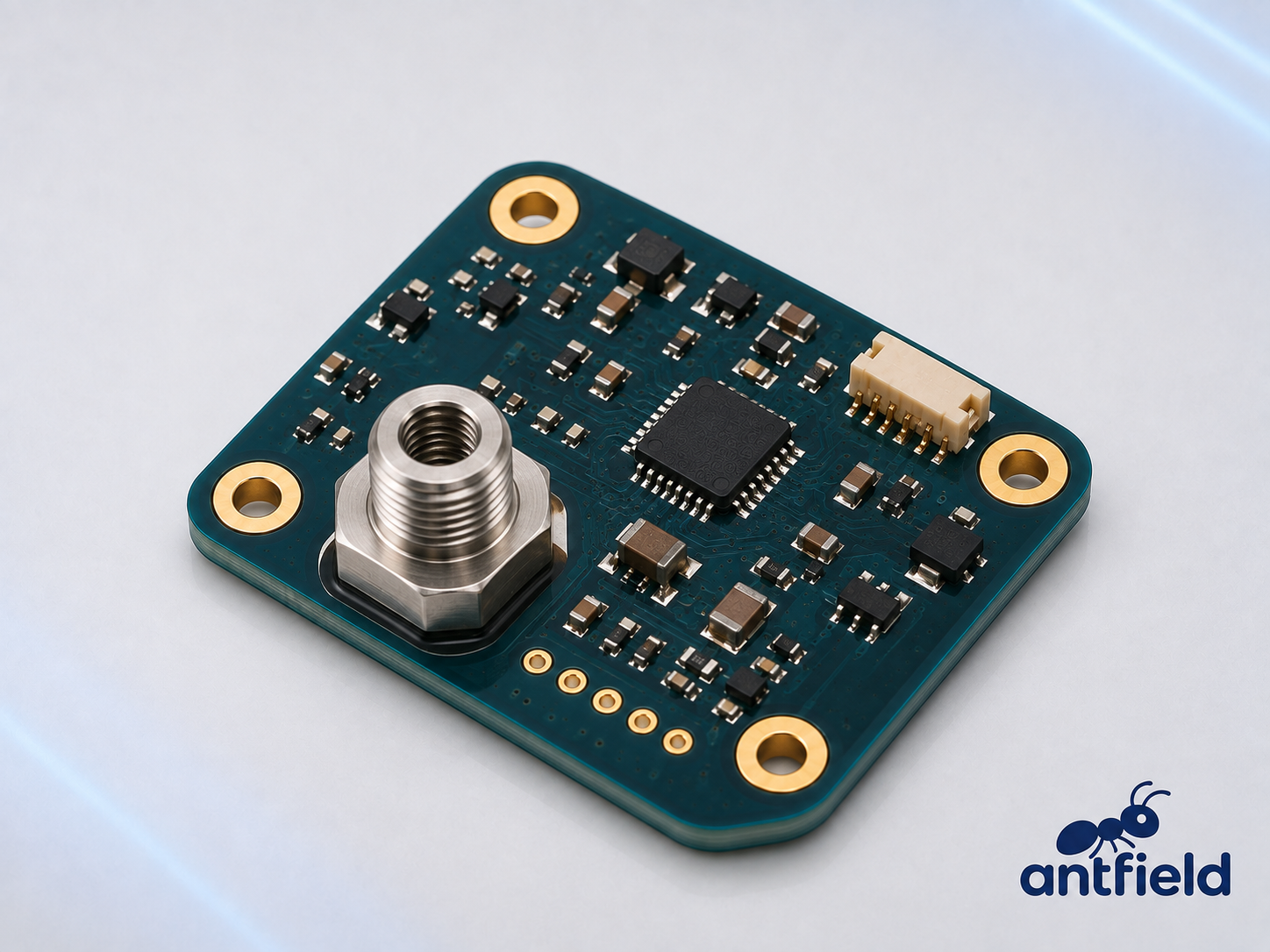
The Antfield Pressure Sensor Module is designed to measuregas or liquid pressure and convert it into an electrical signal for roboticcontrol systems. It provides real-time pressure feedback for pneumaticactuators, vacuum grippers, hydraulic systems and other pressure-dependentrobotic applications.
In a robotic vacuum-gripping system, the modulecontinuously monitors the negative pressure inside the suction line. It helpsthe controller confirm that the workpiece has been securely gripped, identifypressure loss and detect possible air leakage before the object is lifted ormoved.
Depending on the sensor configuration, the module cansupport gauge, absolute, differential or vacuum-pressure measurement. Pressurerange, accuracy, response time, output type, communication interface and PCBdesign can be customized for different robotic projects.
Main Functions
Real-time pressure measurement
Vacuum and negative-pressure monitoring
Suction-grip confirmation
Pneumatic pressure feedback
Hydraulic pressure monitoring
Air-leak and pressure-loss detection
Overpressure and underpressure detection
Closed-loop pressure control
System-condition monitoring
Applications
Robot vacuum grippers
Pneumatic robotic actuators
Hydraulic robot systems
Soft robotic grippers
Industrial robotic arms
Medical and rehabilitation robots
AGV and AMR pneumatic systems
Automated pick-and-place equipment
Fluid-handling and dispensing robots
Robotic leak-testing equipment
Main Components of the Current Sensor Module
Component | Function |
High-Current Copper Busbar | Carries the measured motor, battery or DC-bus current through the sensing area with low electrical resistance. |
Hall-Effect Current Sensor IC | Detects the magnetic field generated by the current flowing through the copper busbar. |
Hall Sensing Element | Converts the magnetic field around the current path into a small electrical signal. It is normally integrated into the sensor IC. |
Magnetic Concentrator—Optional | Concentrates the magnetic field around the sensing element to improve sensitivity and measurement range. |
Isolation Barrier | Separates the high-current circuit from the low-voltage measurement and control circuit. |
Signal Amplifier | Amplifies the original Hall-sensor signal for accurate processing. It may be integrated into the current sensor IC. |
Analog-to-Digital Converter—Optional | Converts the analog current signal into digital measurement data. |
Voltage Reference | Provides a stable reference for accurate analog current measurement. |
MCU or Processing IC—Optional | Performs calibration, filtering, current calculation, alarm detection and communication management. |
Temperature Sensor—Optional | Supports compensation for offset and sensitivity changes caused by busbar and ambient temperature. |
Voltage Regulator | Supplies stable operating voltage to the sensing and processing circuits. |
Output Driver or Transceiver | Generates analog, PWM or digital communication signals for the robot controller. |
ESD and Transient Protection | Protects the low-voltage interface against electrostatic discharge and voltage transients. |
Reverse-Polarity Protection | Helps prevent module damage if the low-voltage power input is connected incorrectly. |
Precision Resistors and Capacitors | Provide power filtering, signal filtering, gain setting and stable operation. |
Power Terminals | Provide secure, low-resistance connections to the battery, motor controller or power-distribution system. |
Signal Connector | Carries power, current data, communication and diagnostic signals to the robot controller. |
PCB and Mounting Holes | Support the electrical circuits and provide secure installation in the robotic system. |
How the Current Sensor Works
When current flows through the copper busbar, it generatesa magnetic field around the conductor. The Hall sensing element measures thismagnetic field and converts it into an electrical signal proportional to thecurrent.
The signal-conditioning circuit amplifies, filters andcompensates the measurement before sending it to the robot controller.
Because the Hall sensing element is electrically separatedfrom the high-current conductor, the module can provide galvanically isolatedmeasurement between:
Depending on the design, it can measure:
Main Functions
Real-time current measurement
Motor-phase current monitoring
DC-bus current monitoring
Battery charge and discharge measurement
Motor torque estimation
Load-condition monitoring
Overcurrent detection
Short-circuit detection support
Motor-stall detection
Energy-consumption measurement
Fault diagnosis
Predictive-maintenance support
Current-Sensing Technologies
Technology | Characteristics | Typical Robotic Use |
Open-Loop Hall Sensor | Electrically isolated, compact and capable of measuring AC and DC current | Motor drives, batteries and general robot power systems |
Closed-Loop Hall Sensor | Higher accuracy and faster response, but usually larger and more expensive | Precision servo drives and industrial robots |
Shunt-Resistor Sensor | Measures voltage drop across a precision resistor; accurate and cost-effective but introduces power loss | Low- and medium-current motor and battery circuits |
Current Transformer | Provides isolation and measures AC current only | AC power systems and high-frequency switching circuits |
Rogowski Coil | Measures changing current with wide bandwidth and no magnetic saturation | High-current pulses and specialized motor-drive testing |
The generated image represents an isolatedopen-loop Hall-effect current sensor module.
Output and Interface Options
Depending on the selected configuration, the module cansupport:
Recommended Specifications for the Product Page
Specification | Description |
Measurement Type | AC, DC, pulsed or bidirectional current |
Nominal Current | Current level intended for continuous measurement |
Measurement Range | Minimum and maximum measurable current |
Peak Current | Maximum current measurable for a limited duration |
Overcurrent Capability | Current the conductor can withstand without damage |
Sensitivity | Output change corresponding to a specific current change |
Accuracy | Difference between measured and actual current |
Offset Error | Output error when no current is flowing |
Linearity | Deviation from an ideal proportional response |
Resolution | Smallest detectable change in current |
Bandwidth | Range of current frequencies the sensor can measure |
Response Time | Time required to respond to a current change |
Isolation Voltage | Maximum voltage separation supported between the power and signal sides |
Creepage and Clearance | PCB spacing between high-voltage and low-voltage conductive parts |
Insertion Resistance | Electrical resistance added by the busbar or sensing path |
Power Loss | Heat generated by the current path during operation |
Temperature Drift | Change in offset and sensitivity over temperature |
Output Type | Analog, PWM or digital communication output |
Supply Voltage | Required low-voltage operating supply |
Operating Temperature | Supported environmental temperature range |
Terminal Size | Mechanical dimensions of the high-current connection |
PCB Dimensions | Module length, width and height |
Installation Considerations
Select a module with sufficient continuous and peak-current ratings.
Confirm the current direction and polarity before installation.
Use correctly sized cables, terminals and fasteners.
Tighten power-terminal bolts to the specified torque.
Keep contact resistance at the terminals as low as possible.
Provide sufficient airflow or thermal conduction around the busbar.
Maintain the required electrical creepage and clearance distances.
Keep the low-voltage signal circuit separated from high-current switching paths.
Use differential signals or suitable digital communication in noisy environments.
Keep the sensor away from unintended strong magnetic fields.
Calibrate the zero-current output after installation.
Consider temperature compensation for high-current applications.
Verify bandwidth when measuring PWM motor-phase current.
Install fuses, contactors or circuit breakers separately when physical current interruption is required.
Important Technical Note
A current sensor measures current but does notnormally disconnect the power circuit by itself.
For overcurrent or short-circuit protection, its outputmust be connected to a controller, gate driver, BMS or protection circuit thatcan operate a MOSFET, contactor, relay, fuse or circuit breaker.
The final measurement accuracy depends on the sensor IC,busbar geometry, magnetic interference, temperature, calibration, PCB layoutand installation quality.


