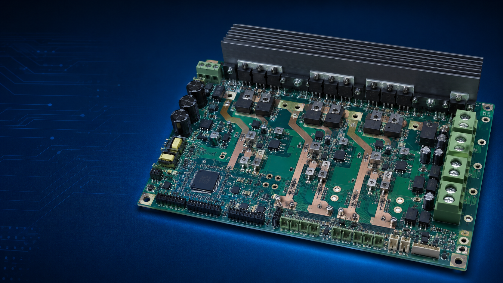
Key Features
PWM speed and direction control
Current, voltage and temperature feedback
Overcurrent, short-circuit and thermal protection
Regenerative energy and braking management
Typical Electronic Components
Power MOSFETs/IGBTs; gate drivers; shunts or Hall-current sensors; DC-link capacitors; TVS devices; inductors; MCU; high-current connectors.
Reference PCB and PCBA Parameters
Reference item | Typical guidance |
Typical layers | 2-8 layers |
Copper | 2-6 oz depending on verified current |
Material | High-Tg FR-4, insulated metal substrate or hybrid construction |
Key processes | Heavy copper, thermal vias, copper inlay/coin where required |
Electrical focus | Creepage, clearance, loop inductance and current density |
Testing | Power-on, load, current-limit, thermal and functional test |
Manufacturing and Engineering Priorities
Minimize gate-drive and high-current commutation loops.
Use Kelvin sensing for shunts and keep analog measurement away from switch nodes.
Size copper using continuous current, peak current, allowable temperature rise and cooling conditions.
Coordinate heat sinks, thermal pads and mounting pressure with the mechanical design.
Design and Commercial Cautions
Do not advertise a current rating without board size, copper thickness, airflow and temperature-rise criteria. Motor-cable transients require suitable TVS, snubber and EMC design. Review regenerative voltage and emergency-stop behavior.
|
Applications
Mobile bases, pumps, fans, cleaning brushes, conveyors and auxiliary actuators.

